Homemade Generator Plan: PERMANENT MAGNET MACHINE
ABSTRACT
The invention provides a magnetic repellent motor which comprises: a shaft (26) which can rotate around it's longitudinal axis, a first set (16) of magnets (14) arranged around the shaft (26) in a rotor (10) for rotation with the shaft, and a second set (42) of magnets (40) arranged in a stator (32) surrounding the rotor. The second set of magnets interacts with the first set of magnets, and the magnets of both sets are at least partially screened so as to concentrate their magnetic field strength in the direction of the gap between the rotor (10) and the stator (32).
BACKGROUND
This invention relates to a magnetic repellent motor, or drive mechanism. Such a mechanism may be useful for driving an electrical generator, a vehicle, a ship, an aircraft, or the like. Conventional power sources rely on fossil fuels or secondary power sources such as nuclear power, or electricity derived by whatever means, for its source of driving power. All of these sources of power suffer from disadvantages such as being the cause of pollution, requiring transportation or transmission over long distances to the point of use, and being costly to purchase. Thus, there is a need for a power source which is substantially pollution-free in operation, requiring substantially no external power, and which is simple to maintain.
SUMMARY
This invention provides a magnetic repellent motor which comprises: a shaft which can rotate about its longitudinal axis, a first set of magnets which are arranged around the shaft and which rotate with the shaft, and a second set of magnets arranged in a stator surrounding the rotor, where the second set of magnets reacts with the first set of magnets, both sets being partially screen magnetically in order to direct their magnetic field into a gap between the two sets of magnets. Thus, the interaction of at least some of the magnets of the first and second sets urge the shaft to rotate.
The interaction may be the net force of like magnetic poles repelling each other thereby urging the magnets away from each other, however, since only the rotor magnets can be moved by this urging force, the shaft is urged to rotate into a position where the repelling force is less.
The rotor may be substantially disc-shaped and the first set of magnets may be located in a peripheral region of the rotor which rotates with the shaft. The stator may be in the form of a pair of arms aligned with the rotor. These stator arms can be moved relative to each other and away from the rotor, in order to allow the gap between the rotor and the stator to be set selectively. The gap may be set manually, for example, by a hand wheel, or automatically, for example by a system of weights which move centrifugally and so form a rotational speed control which acts automatically, i.e. the smaller the gap, the greater the repulsion forces between the magnets of the rotor and stator.
Both the rotor and the stator may have more than one set of magnets. The magnets may be placed in sockets which extend towards the circumference of the rotor. These sockets may be substantially cylindrical and arranged in a plane which is perpendicular to the longitudinal axis of the rotor shaft. These sockets may also be arranged at an acute angle relative to the tangent to the circumference of the rotor disc where the mouth of the cylindrical socket is located. Similarly, the stator magnet sockets may be angled relative to the inner circumference of the stator. These angles may be between 18 degrees and 40 degrees, but preferably between 30 degrees and 35 degrees.
These sockets may have a socket lining consisting at least partially of a magnetic screening material. The socket lining may line the entire extent of the sockets so that only the opening to the exterior remains unlined. In another embodiment of the invention, the magnetic screen lining may cover a substantial percentage of the whole of the socket lining, e.g. 50% of the socket lining.
The magnets may be Nd-Fe-B of dimensions which fit snugly inside the linings of the sockets. These magnets may be cylindrical in shape and have a 37 mm diameter, a 75 mm length and a magnetic strength of 360,000 gauss. The socket lining, magnetic shield and magnet may all have a hole through them to receive a securing pin, preferably positioned so that it is parallel to the longitudinal axis of the shaft.
The number of sockets in the rotor and the corresponding stator may differ so that there is not a one-to-one relationship between the sockets in the rotor and the sockets in the corresponding stator. Similarly, the number of magnets in any additional rotor/stator sets may differ from the first rotor/stator sets in order that the two sets are out of register at any given time. Some sockets may be left empty in either the rotor or the corresponding stator, or both. The motor may have one or more rotor/stator pairs of this type arranged in a stack. It is preferable for the magnets of adjacent rotors to be out of register, i.e. staggered or offset relative to each other.
DESCRIPTION OF THE DRAWINGS


Fig.3 is a perspective view showing a left arm of a stator.

Fig.4 is a perspective view showing a right arm of a stator

Fig.5 is a perspective view showing a stack of the stators or Fig.3 and Fig.4 in an assembled arrangement.


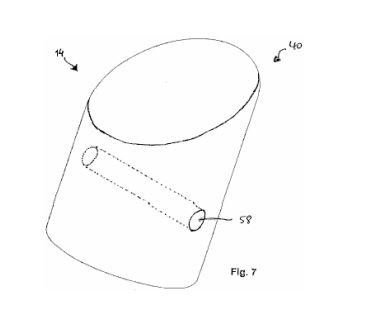
Fig.7 is a perspective view showing one of the magnets

💠 Harnessing the power of back electromagnetic fields (Back EMF)
💠 Back EMF generates Lenz's Force in generator 💠 When the output energy is not affected by the Lenz (free) force, a self-powered mechanism will be established from the AC generator head to the induction motor. And the kinetic energy of the induction motor at that time was only supposed to stir the Ether by Nikola Tesla's "Rotating Magnetic Field". That's the mechanism for a Free Energy AC generator - no fuel needed - Self-powered generator.
AC generator without fuel: Free Energy Will Change Our World Forever
👉 Free Energy AC generator
DESCRIPTION OF PREFERRED EMBODIMENTS


As shown in Fig.2, the sockets 18, receive (or incorporate) a socket lining 28 (shown in more detail in later figures) which is at least partially made of a magnetic screening material, whether metallic or non-metallic, for example, graphite. The socket lining 28, covers the entire extent of the sockets 18, so that only the opening to the exterior remains uncovered.


Referring to Fig.6, a socket lining 28, 50 of the rotor disc 10, or the stator 32, is shown in more detail. The socket lining 28, 50 is formed to fit into the sockets 18, 44 and may be made completely of a material which has magnetic screening properties. In one preferred embodiment, the socket lining 28, 50 is made of diamagnetic graphite and is partially surrounded by an additional shield 52 of a material having strong magnetic screening properties, e.g. stainless steel. In the embodiment shown in Fig.6, the shield 52 surrounds about 50% of the socket lining surface.

💠 Harnessing the power of back electromagnetic fields (Back EMF)
💠 Back EMF generates Lenz's Force in generator 💠 When the output energy is not affected by the Lenz (free) force, a self-powered mechanism will be established from the AC generator head to the induction motor. And the kinetic energy of the induction motor at that time was only supposed to stir the Ether by Nikola Tesla's "Rotating Magnetic Field". That's the mechanism for a Free Energy AC generator - no fuel needed - Self-powered generator.
AC generator without fuel: Free Energy Will Change Our World Forever
👉 Free Energy AC generator


