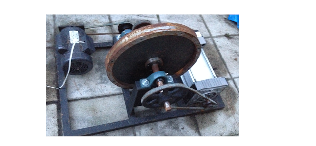
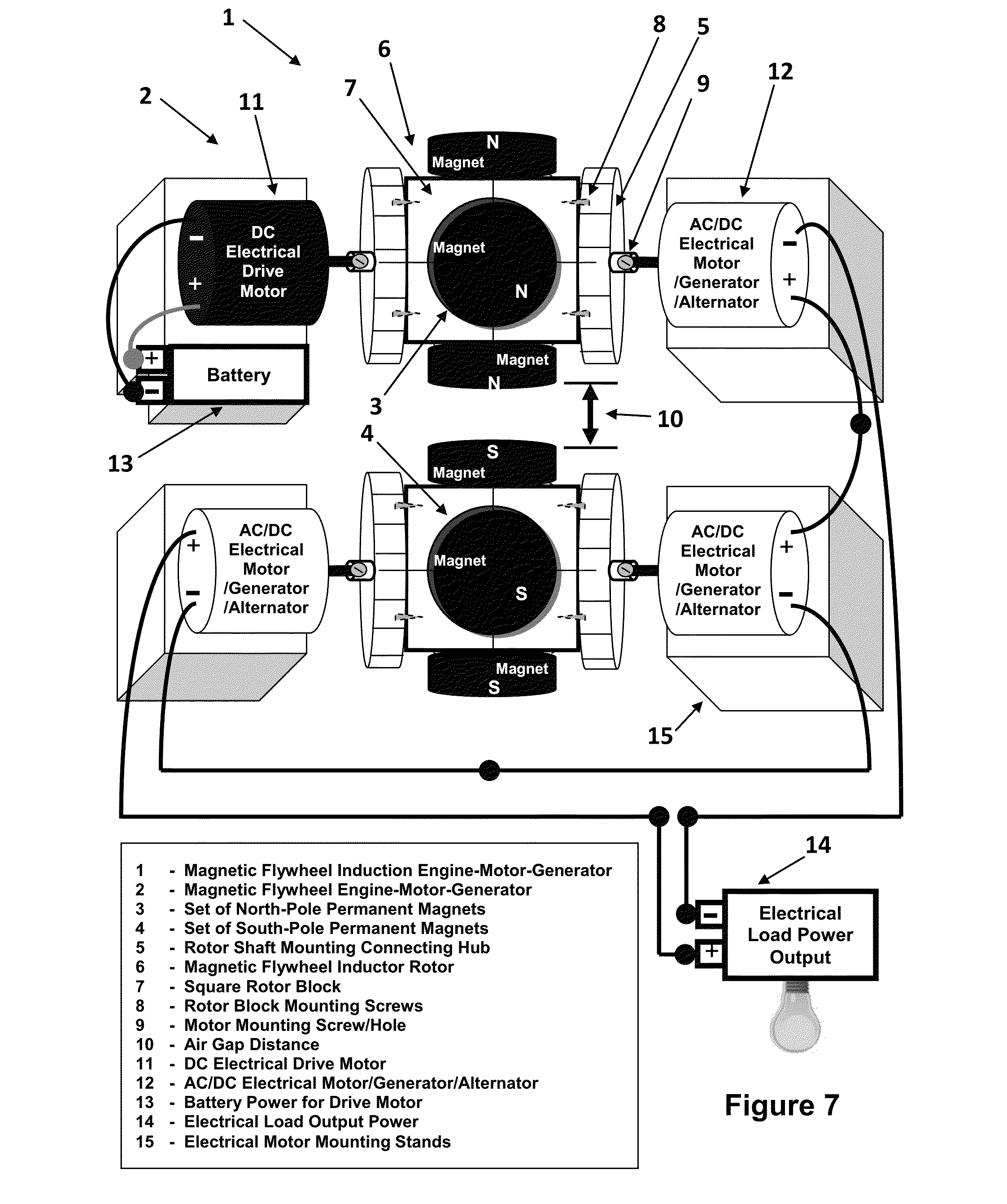
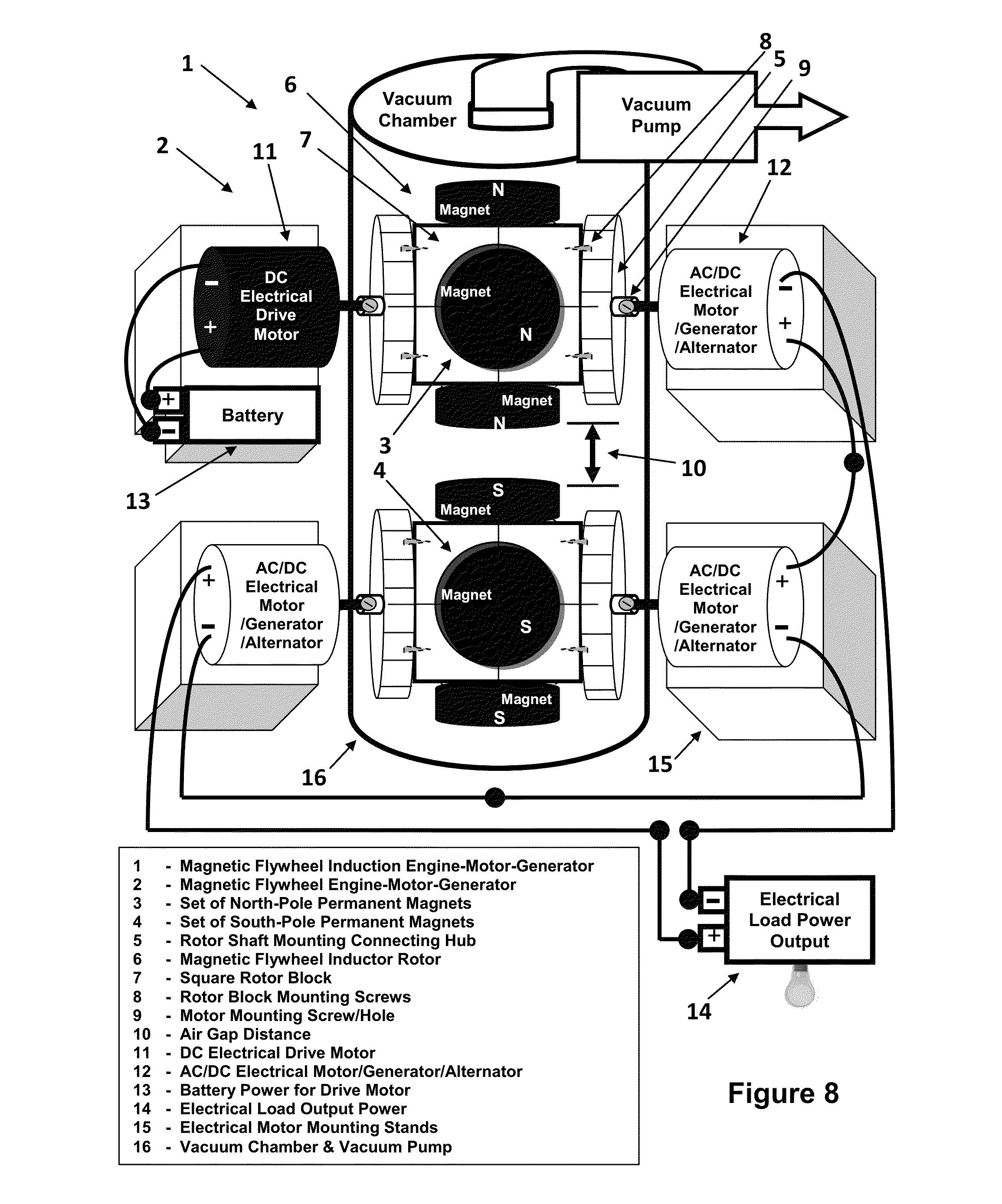
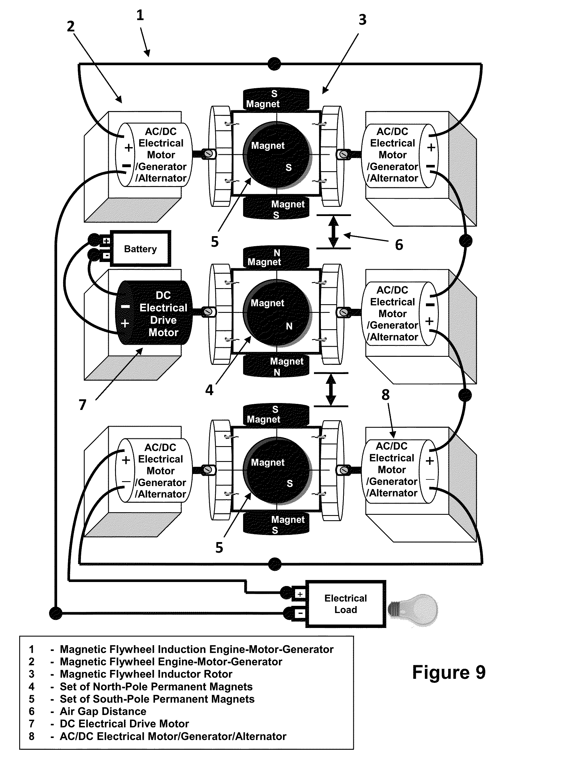
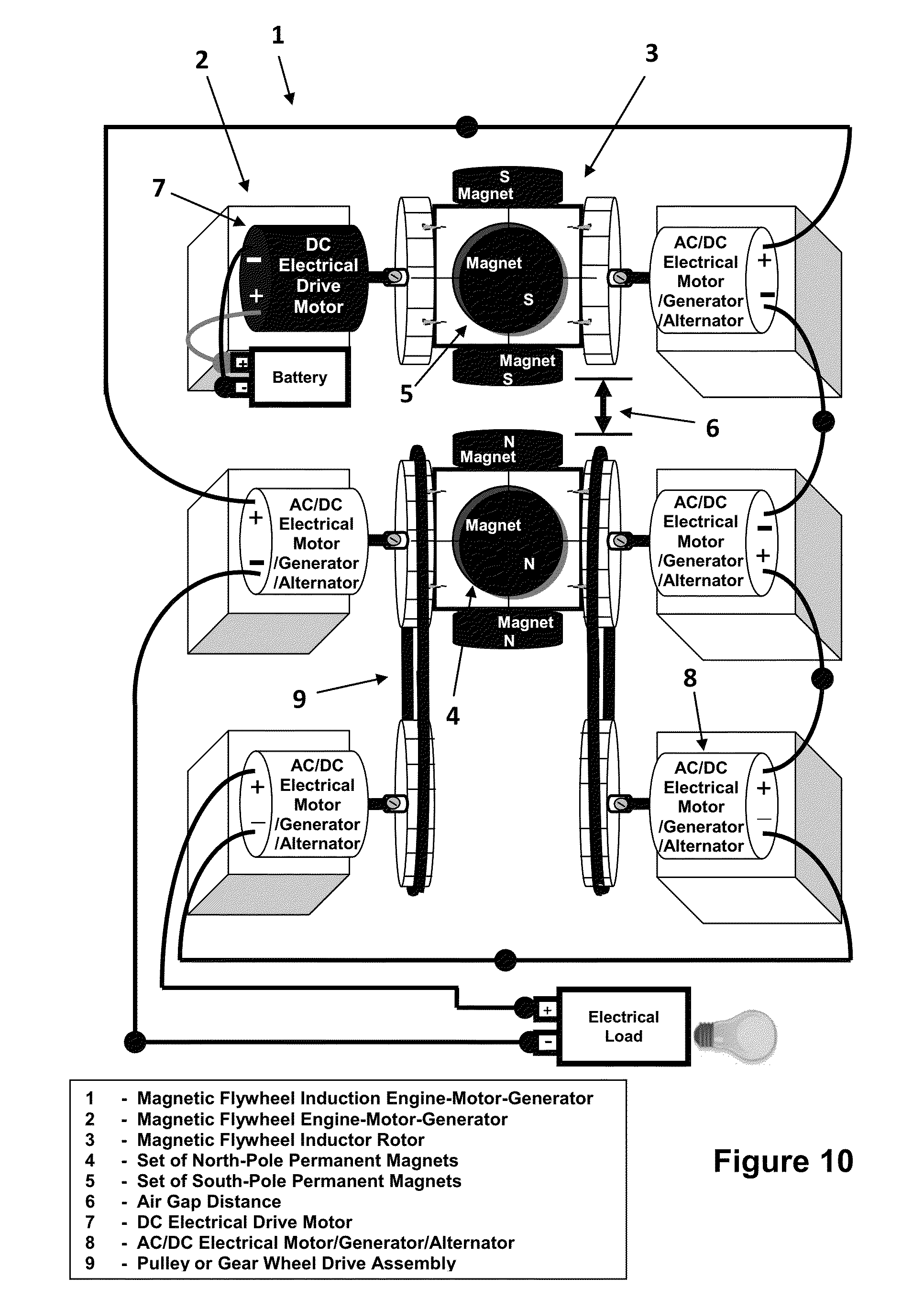
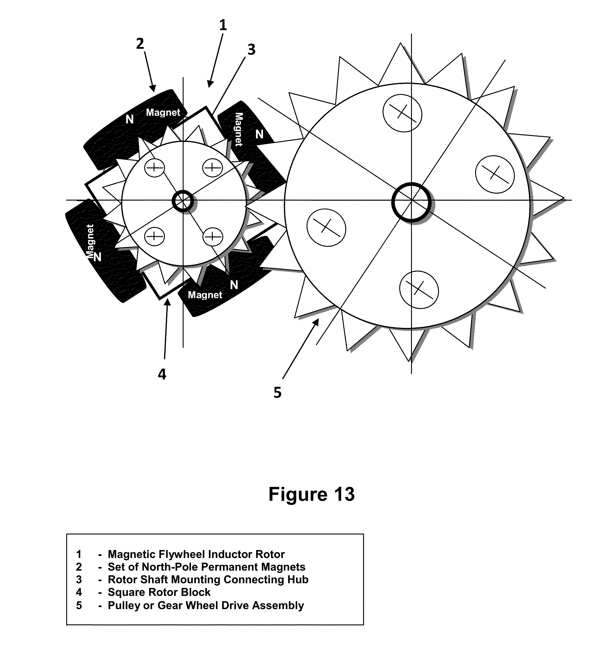
It is a free energy machine that is either mechanically started or electrically started. After the start-up process, this free-energy machine does not need any external kinetic energy, or external power supply. It works on feedback from kinetic or electrical energy.
In terms of form, it's a self-powered generator. In fact, it is a free energy machine with output energy greater than input energy, based on self-powered mechanism (feedback to input) to create Self Powered Magnetic Generator.
That which is claimed is:
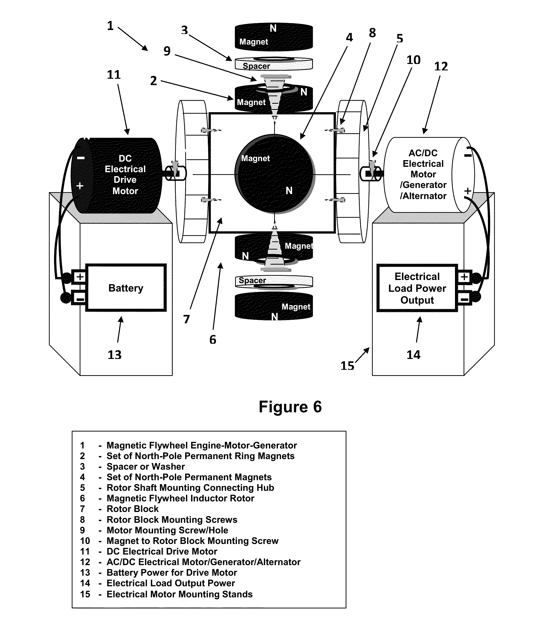
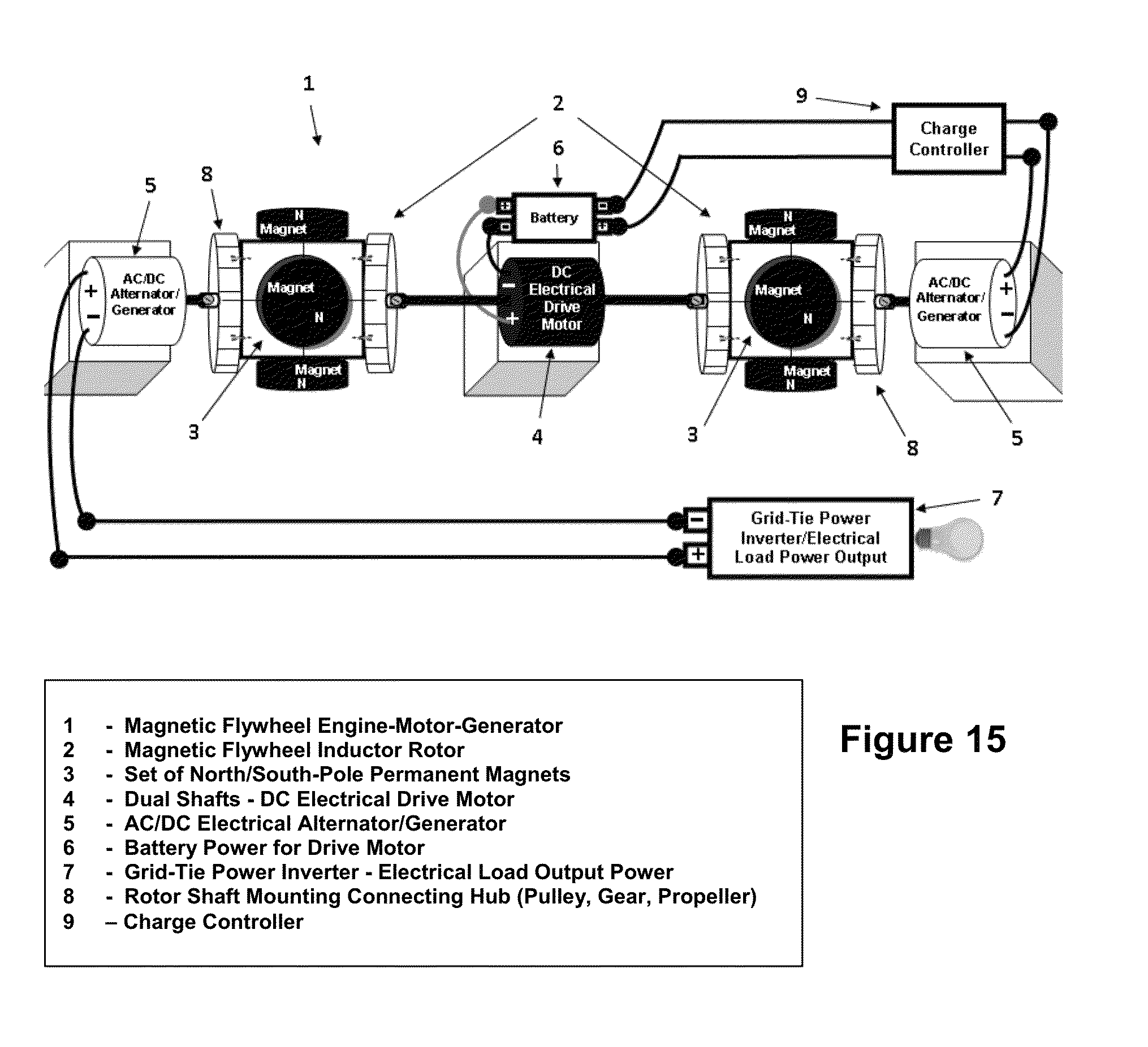
1. The apparatus makes the claim of invention known as a “Magnetic Flywheel Engine-Motor-Generator”, described in limited scope is constructed: a minimum of one (1) “Magnetic Flywheel Inductor Rotor”, one (1) “Prime-Mover” motor with extended shafts, and one (1) “Alternator/Generator”, mounted on separate bases, and positioned with shafts front facing oppositely (shafts facing shaft), which includes dual shaft motors; when combined as an apparatus, is used for generating direct current (DC) electrical power, alternating current (AC) electrical power, or acts as a mechanical mover doing work, which includes: turning a rotor, gear, pulley, tire rim, fan, or drive wheel, pumps, propellers, propelling vehicles/aircraft/marine, and various mechanical and electromechanically devices, not mentioned herein.
2. The apparatus according to claim 1, further claims, when any minimum of one (1) or more “prime movers” is an “Electric Motor/Generator” which is powered, it is designated a “Drive Motor”, and the others unpowered DC/AC Generators/Alternators, attached to rotating “Magnetic Flywheel Inductor Rotors”, typically function as a “DC Electrical Power Generator” or an “AC Electrical Power Generator”, which supplies power, used to recharge batteries, and power various electronics, appliances, electric vehicles, motors, and supply power back to a mains power grid.
3. The apparatus according to claim 1, and claim 2, further claims, when all “Electric Motor/Generators” are powered, they are all designated “Drive Motors”; and the “Magnetic Flywheel Engine-Motor-Generator” apparatus, functions as a mechanical mover doing work, which includes: turning a rotor, gear, pulley, tire rim, fan, or drive wheel, pumps, motors, propelling vehicles/aircraft/marine, and various mechanical and electromechanically devices, not mentioned herein.
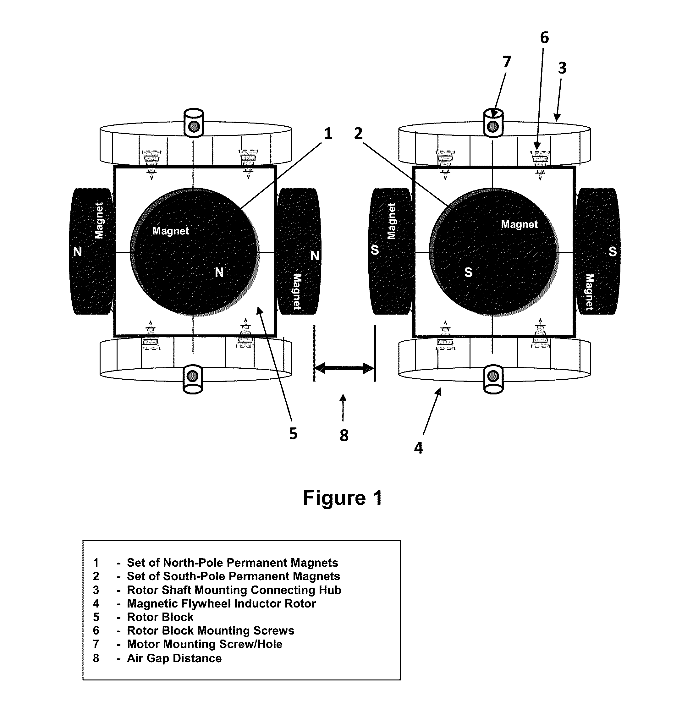
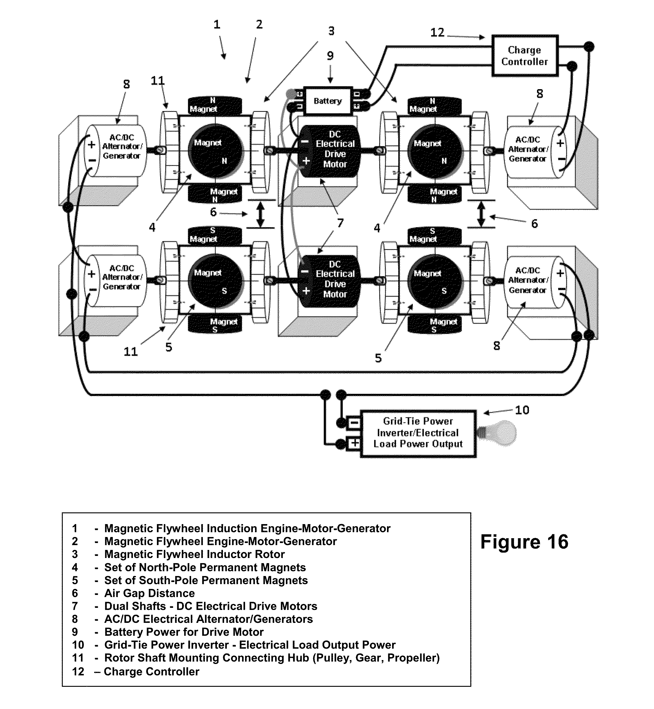
4. The apparatus makes further claims extending the depth of invention according to claim 1, for combining a plurality of two (2) or more adjacently spaced “Magnetic Flywheel Engine-Motor-Generators”, separated with a small “Air Gap” distance, between their respective “Magnetic Flywheel Inductor Rotor” permanent magnets surfaces; this constructs a different apparatus as described herein, known as a “Magnetic Flywheel Induction Engine-Motor-Generator” constructed of: a minimum of two (2) “Magnetic Flywheel Inductor Rotors”, two (2) “Prime-Mover” motors with extended shafts (including dual shafts), two (2) “Alternator/Generators”, and an “Air Gap Distance” separating the “Magnetic Flywheel Inductor Rotor” permanent magnets surfaces.
5. The apparatus makes claims, according to claim 4, a “Magnetic Flywheel Induction Engine-Motor-Generator” uses the new physics of “magnetic induction”, harvesting waste rotational mechanical energy, collected in the “Rotary Magnetic Fields” of the “Magnetic Flywheel Induction Rotors”, lost by the “Drive Motor/s”, used to power and mechanically drive the rotation of “Magnetic Flywheel Induction Rotors” about their respective axis of the motor shafts; and when attached to “Electrical Alternator/Generators” is used for generating direct current (DC) electrical power, alternating current (AC) electrical power, or acts as a mechanical mover doing work, which includes: turning a rotor, gear, pulley, tire rim, fan, or drive wheel, pumps, propellers, motors, propelling vehicles/aircraft/marine, and various mechanical and electromechanically devices, not mentioned herein.
6. The apparatus according to claim 4, further claims, when limiting the invention described herein to two (2) “Magnetic Flywheel Induction Rotors”, two (2) “prime-mover” “Dual Shafts Electrical Motor/Generators”, and four (4) “DC/AC Alternator/Generators”, and when any one (1) or both “prime-mover” “Electrical “Drive” Motor/Generators” is powered, wherein the four (4) “DC/AC Alternator/Generators” are not powered, but is attached via motor shafts and connecting hubs, to each of the four (4) “Magnetic Flywheel Induction Rotors”, the apparatus functions as “DC/AC Electrical Power Generator”, where the power is supplied by the “DC/AC Alternator/Generators”.
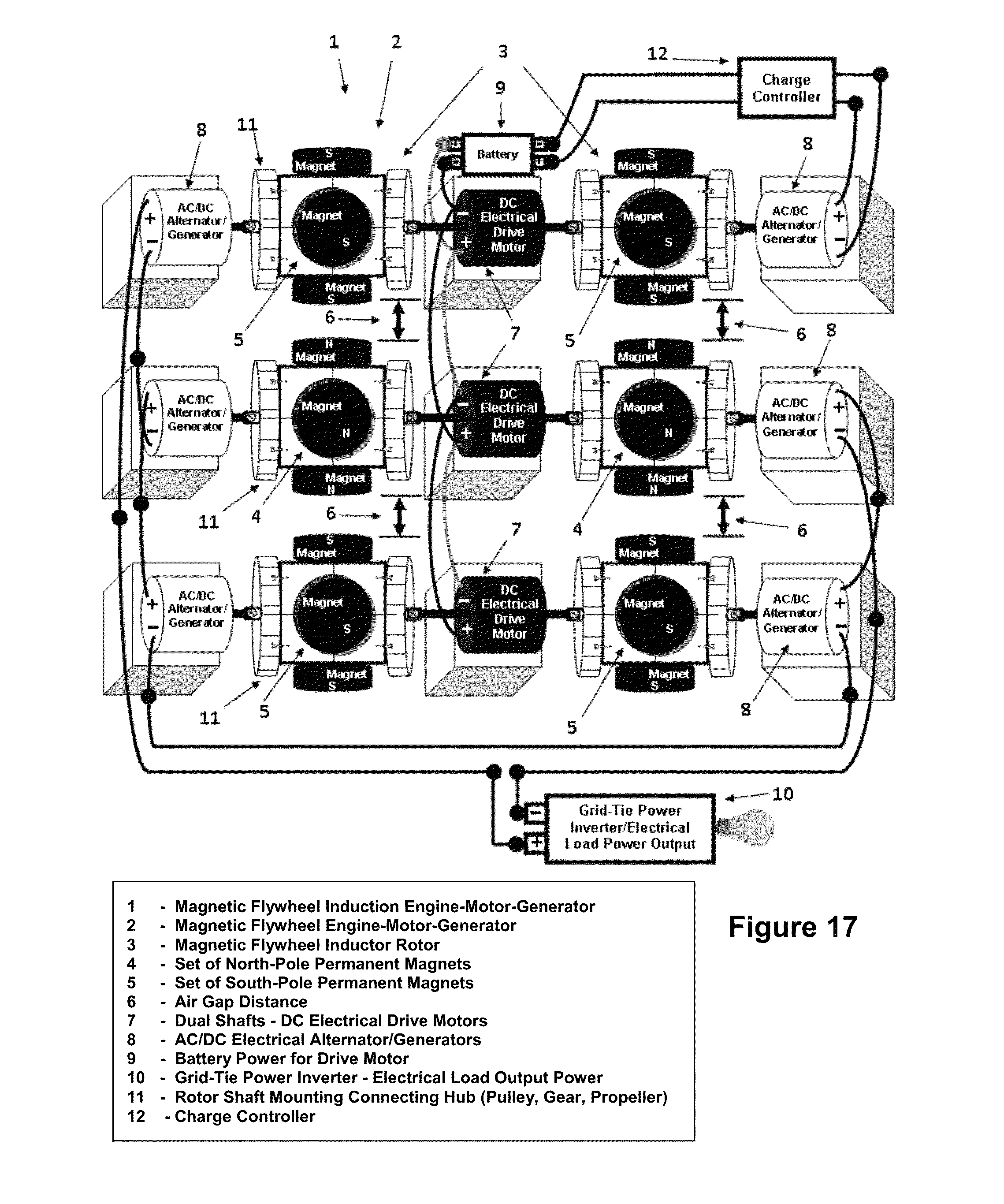
7. The apparatus according to claim 1, claim 4, and claim 6, further claims, for the purpose of increasing the AC/DC electrical power output of invented apparatus, and or mechanical work output, is accomplished by attaching any plural pair of adjacently spaced “Magnetic Flywheel Engine-Motor-Generators”, each aligned and stacked together, separated by an “Air Gap Distance” between their respective “Magnetic Flywheel Inductor Rotors” permanent magnets surfaces; this is also an apparatus known as a “Magnetic Flywheel Induction Engine-Motor-Generator”, as claimed therein.
8. The apparatus according to claim 1, claim 4, claim 6, and claim 7, makes further claims, for greatly increasing the output efficiency, of a “Magnetic Flywheel Induction Engine-Motor-Generator”, by housing and enclosing the “Magnetic Flywheel Inductor Rotors”, in an optional vacuum chamber, during normal operation; and where all of the “Electric Motors/Alternators/Generators” with their extending motor shafts, connected to the “Magnetic Flywheel Inductor Rotors”, remain outside of the vacuum chamber, for greatly improved output efficiency of the apparatus.
9. The apparatus makes claims, according to claim 1, claim 4, claim 6, and claim 7, the “Magnetic Flywheel Induction Engine-Motor-Generator”, and its construction are not limited to “Electrical Motor/Generators/Alternators” only; but any “Prime-Mover”, including fossil fuel engines, with a motor shaft, could be used as “Drive Motors” to power the apparatus.
10. The apparatus according to invention, makes further claims, a single “Magnetic Flywheel Induction Rotor”, is a “Magnetic Monopole”, rotatable permanent magnet rotor block apparatus, which rotates about motor shafts axis; and where greater values in output efficiency of the apparatus, are based on a designated geometric “Rotor Block” shape, specific number of facet surfaces of block, total mass/inertia of rotor block, and the magnetic strength on the facets surfaces.
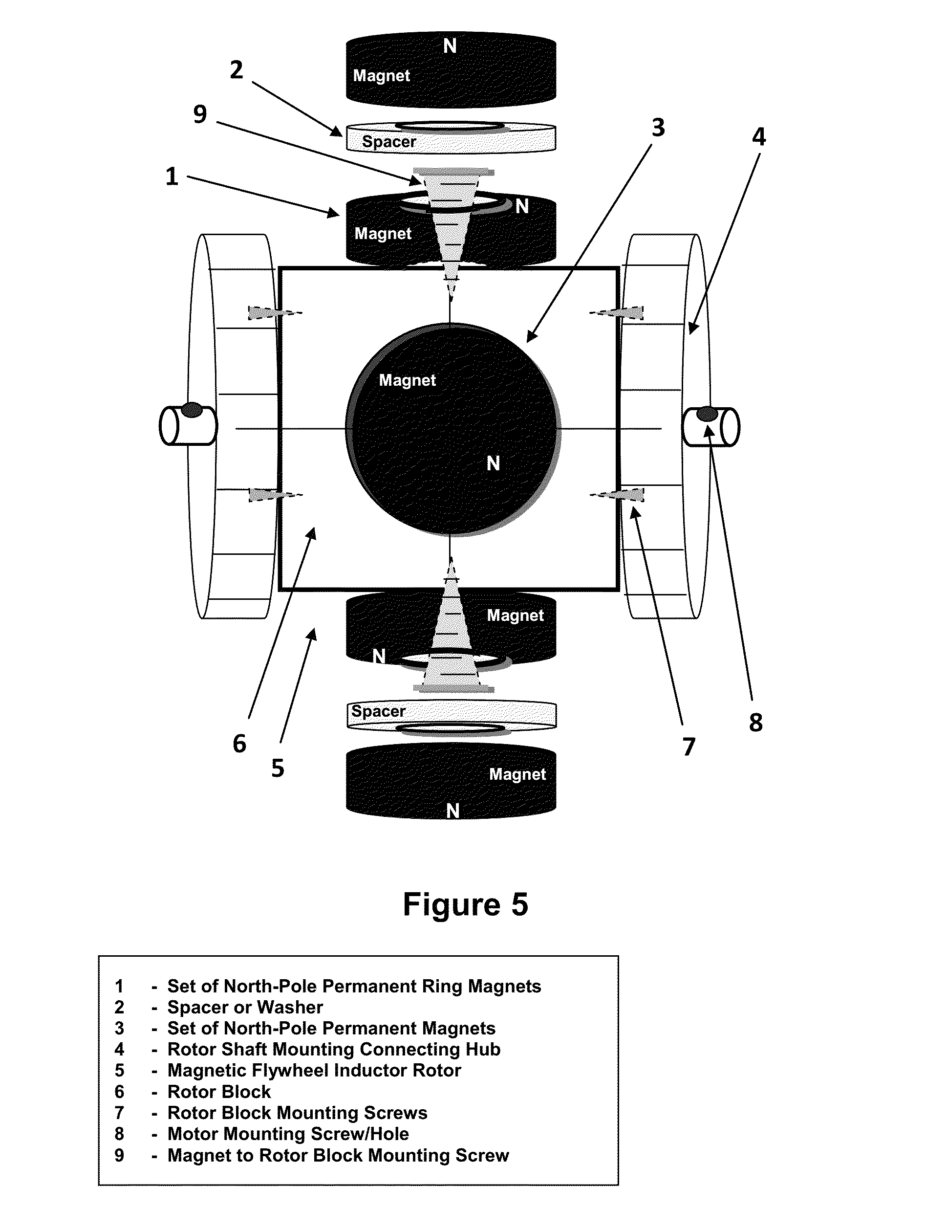
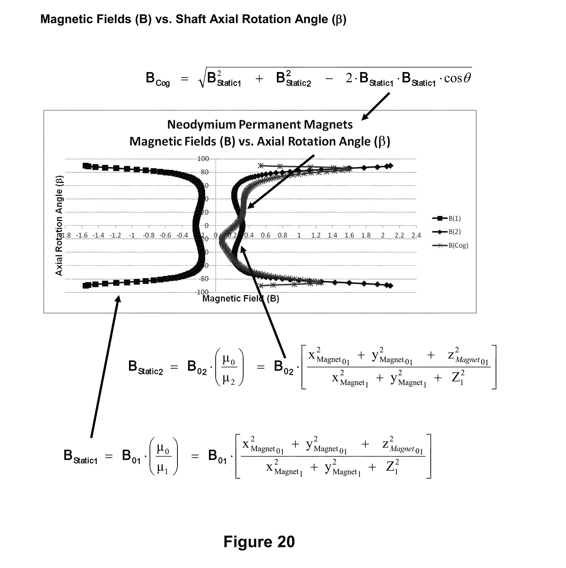
11. The apparatus according to claim 10, a single “Magnetic Flywheel Induction Rotor” is “Magnetic Monopole”, constructed of three main components: a single “Rotor Block”, and two (2) “Rotor Shaft Mounting Hub Connectors” attached on the left and right sides of the rotor block, and a set of Neodymium Permanent Magnets, with identical magnetic pole strength, attached to each facet surface, and circumference of the “Magnetic Flywheel Induction Rotor” block.
12. The apparatus according to claim 10 and claim 11, a single “Magnetic Flywheel Induction Rotor Block” has a designated geometric rotor block shape, and number of facets side surfaces on the circumference of rotor block, which determine the output efficiency of the engine-motor-generator; where more facets surfaces, equals greater efficiency in rotation output: Triangle (5 five sides), Square (6 six sides), Pentagon (7 seven sides), Hexagon (8 eight sides), Octagon (10 ten sides), Rectangle (6 six sides), cylinder (3 three sides), or Disk shaped Block (3 three sides).
13. The apparatus according to claim 1, claim 4, claim 6, and claim 10, further claims, any “prime-mover” or “Motor/Generators/Alternators” with an extended motor shaft, can be connected to the “Magnetic Flywheel Induction Rotor Block”, via the “Rotor Shaft Mounting Hubs”, attached to the left and right sides of the “Flywheel Rotor Block”; and is an apparatus which connects various types of “Motor/Generators/Alternators” in different configurations to the “Magnetic Flywheel Induction Rotor Blocks”.
14. The apparatus according to claim 11, further claims, any attachment that connects and joins a “prime-mover” or “Motor/Generators/Alternators” with an extended shaft, to the “Magnetic Flywheel Inductor Rotor Block”, is considered a “Motor Shaft Mounting Hub Connector”; and is also considered: Rotor, Gear, Pulley Wheel, Tire Rim, Fan/Blade Assembly, Propeller Assembly, or Drive Wheel, which includes any rotating attachment, used for converting shaft rotational energy and motion, into mechanical work.
15. The apparatus according to claim 10 and claim 11, which further claims, a single “Monopole” “Magnetic Flywheel Induction Rotor” with a specific geometric Rotor Block shape, reserves the top, bottom, front, and rear, facet circumference surface sides, of the “Flywheel Rotor Block”, for the arrangement and attachment of “Permanent Magnets”; with identical magnetic “north poles” or “south poles” facing on the facet surface circumference, of a single “Monopole” “Magnetic Flywheel Induction Rotor”.
16. The apparatus according to claim 10, claim 11, and claim 15, further claims, a single “Monopole” “Magnetic Flywheel Inductor Rotor Block” has attached permanent magnets that are Neodymium (Sintered Neodymium-Iron-Boron (NdFeB)), for the greatest output efficiency of the apparatus. However ceramic permanent magnets, and other permanent magnet materials can also be used, but their rotational motion output efficiencies are lower.
17. The apparatus according to claim 10, claim 11, claim 15, and claim 16, a single “Monopole” “Magnetic Flywheel Inductor Rotor Block” has a designated rotor block shape, and a minimum set of permanent magnet surfaces, per Flywheel Rotor Block: Triangle (3 three magnet surfaces), Square (4 four magnet surfaces), Pentagon (5 five magnet surfaces), Hexagon (6 six magnet surfaces), Octagon (8 eight magnet surfaces), Rectangle (4 four magnet surfaces), cylinder (4 four magnet surfaces), or Disk shaped Block (4 four magnet surfaces); whereas the greater the number of geometric facets or magnet surfaces to a rotor block, the greater the rotational motion, output efficiency of the engine-motor-generator.
18. The apparatus according to claim 1, claim 4, claim 6, and claim 7, makes further claims of a “Magnetic Induction” construction method, where a “Magnetic Flywheel Induction Engine-Motor-Generator”, is constructed with a minimum of two (2) adjacently spaced monopole “Magnetic Flywheel Induction Rotors”, and separating the two flywheel rotors, and their respective unlike magnetic “north” and “south” poles facet surfaces, is an “Air Gap Distance” with typically a minimum distance, of one half the diameter of the magnet surface; and each left and right side of the magnetic flywheel rotor is connected to independent motor shafts and connecting hubs, where motors/generators/alternators are attached, thus, declared herein as a “Magnetic Induction” construction method.
19. The apparatus according to claim 18, makes further claims, for a “Magnetic Induction” process, which occurs when two (2) or more adjacently spaced “Magnetic Flywheel Induction Rotors” and their permanent magnet unlike pole facet surfaces, are separated from one another with a minimum “Air Gap Distance”, of one half the diameter of the magnet surface; and once the “Drive Motor/s” are powered and the “Magnetic Flywheel Induction Rotors” are in rotary motion, the interaction of the “Rotary Magnetic Fields” induces a new rotation into the air gap which causes rotation via magnetic induction of the “Magnetic Flywheel Inductor Rotor Blocks” about their respective motor shafts in the opposition direction to that which created the induction; and when attached to “Motor/Generators/Alternators” produce AC or DC electrical power, while simultaneously providing a means for generating mechanical work output, greatly improving the output efficiency of the engines, motor, and generators.
20. The apparatus according to claim 1, claim 4, claim 6, and claim 7, further claims, a “Magnetic Flywheel Induction Engine-Motor-Generator”, functions as an “AC Electrical Power Generator” when various coils of magnetic wire, are positioned in various ways around, and in the local vicinity of the rotatable “Magnetic Flywheel Induction Rotors”, and in the “Rotary Magnetic Fields” that they generate; the apparatus functions with or without a commutator, or slip-ring, and the output result is “AC Electrical Power” will be generated in the coils of wire.
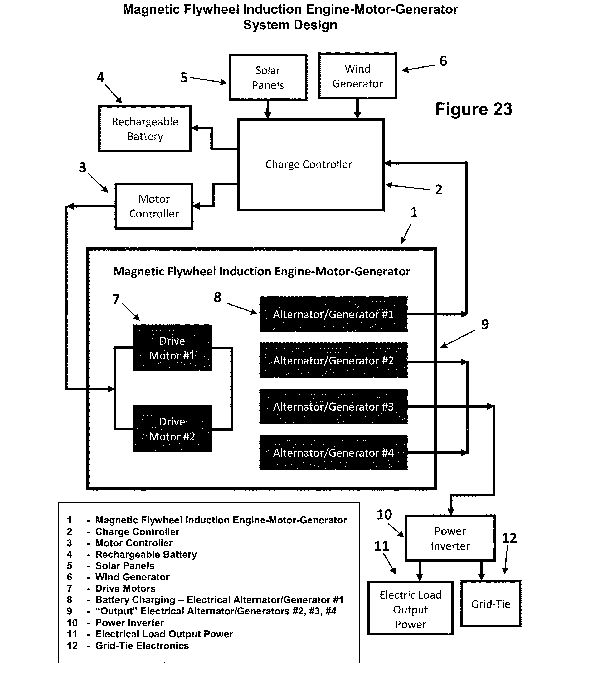
21. The apparatus according to claim 1, claim 4, claim 6, and claim 7, further claims, a “Magnetic Flywheel Induction Engine-Motor-Generator”, closed system design that is “self-sustaining”, given, the system “Drive Motor” is powered by a “Rechargeable Battery” source, the “system” reacts “self-sustaining” by connecting the electrical output power, from one or more of the “DC/AC Electrical Motors/Generators/Alternators”, to a “Charge Controller”, or directly to the “Rechargeable Battery” source; the remaining “DC/AC Electrical Motors/Generators/Alternator/s”, output power, allows the apparatus to function as a “power-plant” and generator, which is “self-sustaining” recharging the battery source, while it produces AC/DC electrical power, and mechanical work.
22. The apparatus according to claim 1, claim 4, claim 6, and claim 7, further claims, a “Magnetic Flywheel Induction Engine-Motor-Generator”, can be utilized and constructed into an aircraft/marine propelling apparatus, when turbine/fan/blades are attached to the rotatable “Magnetic Flywheel Induction Rotors”, and engine nacelles are configured to fit cylindrically around the Magnetic Flywheel Induction Engine-Motor-Generator”, and attached to a aircraft/marine frame.
23. The apparatus according to claim 1, claim 4, claim 6, and claim 7, further claims, a “Magnetic Flywheel Induction Engine-Motor-Generator”, can be utilized and constructed into an automotive/motor cycle/scooter propelling apparatus, when some form of axle, rims and tires are attached to the rotatable “Magnetic Flywheel Induction Rotors”, and the “DC/AC Electrical Motors/Generators/Alternator/s”, which are configured and attached to a automotive/motor cycle/scooter frame.
24. The apparatus according to claim 1, claim 4, claim 6, and claim 7, further claims, a “Magnetic Flywheel Induction Engine-Motor-Generator”, can be utilized as an electrical power source for existing electric cars, by replacing the “rechargeable battery” of the electric car with the “Magnetic Flywheel Induction Engine-Motor-Generator”.
25. The apparatus according to claim 1, claim 4, claim 6, and claim 7, further claims, a “Magnetic Flywheel Induction Engine-Motor-Generator”, can be utilized and constructed into a “personal power plant”, such that when the “Drive Motors” are powered by a fossil fuel, wind energy, solar energy, or rechargeable battery source, the output power supplied by the “DC/AC Electrical Motors/Generators/Alternator/s when connected to a “Power Inverter” can be used to power houses, buildings, campers, hotels, etc; or when connected to a grid-tie inverter, can supply power back to a mains electricity power grid.
